
Modern electronics manufacturing and microelectronic repair demand rigorous thermal discipline. When working with multilayer printed circuit boards, selecting the right soldering equipment determines whether a rework task yields a reliable joint or permanently damages expensive silicon. The transition toward high-density interconnects and lead-free alloys leaves negligible tolerance for temperature fluctuation. Every bench technician faces the challenge of delivering rapid thermal energy without inducing trace delamination, joint embrittlement, or dielectric blistering. Operating professional soldering equipment with responsive thermal regulation helps sensitive substrate assemblies endure repeatable assembly and desoldering cycles.
Thermal management during soldering is often counterintuitive. Technicians often increase operating temperatures to overcome poor heat transfer, but this approach quickly destroys printed circuit board pads. Proper thermodynamic delivery depends on thermal capacity and heat replenishment rather than sheer temperature. Conductive heat flow depends on the temperature gradient between tip and joint, the materials involved, and the quality of surface contact, as described by Fourier’s law of thermal conduction. Separately, a soldering station’s feedback control can help the tip recover lost heat quickly after contact, which reduces how much an operator needs to rely on excessive temperature offsets to compensate for heat loss.
Basic fixed-temperature soldering irons rely on a resistive heating element with no active sensing of the tip’s actual temperature during use. As their copper tips contact heavy copper ground pours, tip temperatures can drop noticeably within seconds on this simpler design. The operator instinctively presses harder or waits, leaving the surrounding fiberglass weave soaked in residual heat. This prolonged heating cycle raises the risk of copper traces separating from the epoxy resin base. Standalone irons that do include thermostatic or sensor-based regulation can behave quite differently, so the real distinction lies in whether a given tool actively measures and corrects its own tip temperature, not simply whether it plugs directly into a wall outlet.
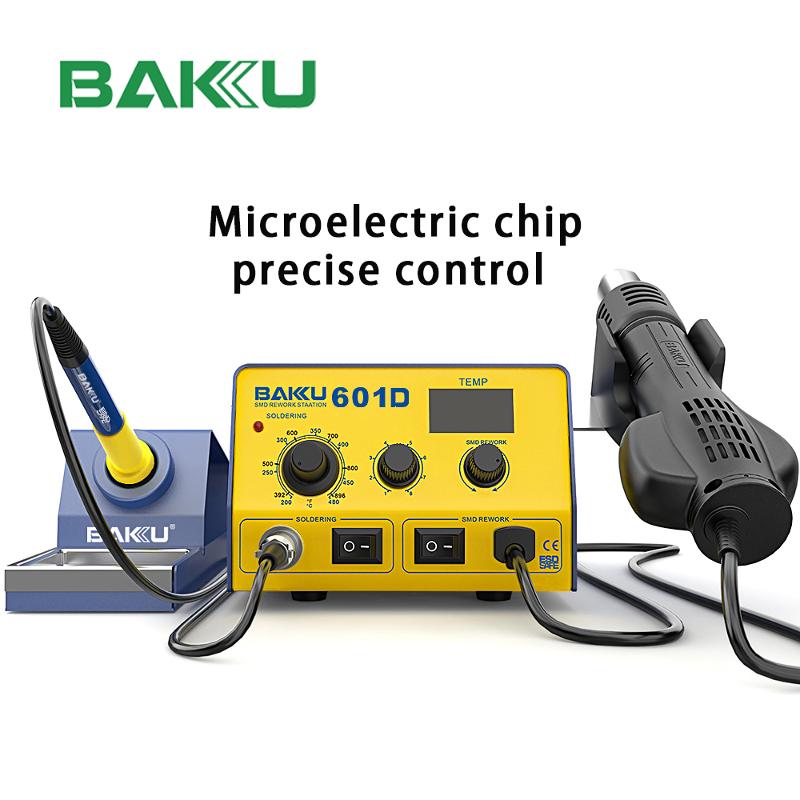
Some microprocessor-controlled soldering stations are designed to reduce this thermal lag through internal temperature sensing and feedback-based power adjustment. Depending on the station’s design, this can allow current delivery to adjust shortly after sensing contact with a cooler surface. A responsive thermal loop of this kind can reduce steep temperature drops, helping keep joint formation within the process window needed for commercial electronics work.
Conductive tip tools handle localized terminals cleanly, but multi-lead surface-mount assemblies require non-contact convective heating. Hot air rework stations transfer energy through heated atmospheric streams, delivering convective heat across quad-flat packages and ball grid arrays rather than touching each lead directly. Whether that heat ends up evenly distributed across the package depends on the nozzle shape, the airflow setting, and how steadily the operator moves the handpiece, so even heating is a matter of setup and technique rather than something the tool guarantees on its own. The physics here shifts from direct conduction to forced fluid convection, which is part of why a hot air tool and a soldering iron are rarely interchangeable on the same repair task.
Controlling airflow velocity helps prevent surface-mount components from shifting during reflow. If air volume surges uncontrollably, tiny passive components like 0201 or 0402 resistors can blow off their solder pads. According to the supplied product specifications for this equipment line, hot air systems in the collection offer an airflow capacity of up to 120L/min. The specific flow rate suited to a given repair still depends on the model in use and the task at hand, so operators should match settings to the nozzle and components involved rather than defaulting to the maximum output.
Temperature stability defines process control on modern rework benches. SAC305, a common lead-free alloy, has a melting range of roughly 217°C to 220°C, running from its solidus to its liquidus temperature, and other lead-free alloys have their own distinct melting ranges. Many bench technicians use iron setpoints somewhere in the 300°C to 370°C range as a starting point, but the appropriate setpoint depends on the specific alloy, tip geometry, joint mass, the soldering station in use, and the thermal limits of nearby components. Rather than treating any single number as a fixed rule, it is worth checking the alloy manufacturer’s guidance and the equipment documentation before settling on a working temperature.
Sub-micron semiconductor gates are vulnerable to electrostatic discharge and electrical leakage from heating elements. A small voltage spike leaking through an ungrounded iron tip can puncture delicate gate oxides in modern microprocessors. Technicians should treat ESD safety as an active electrical safeguard, not just passive antistatic plastic.
ESD test standards such as ANSI/ESD S13.1 define methods for checking tip-to-ground resistance, tip voltage, and leakage current on soldering tools, rather than specifying one universal pass or fail number for every program. In practice, this means ESD-safe soldering equipment should be tested against the applicable standard and the specific program’s acceptance limits rather than a general rule of thumb. The supplied product information describes equipment in this collection as incorporating ESD-safe designs, though the specific grounding or dissipative construction details are not listed; readers should check the individual model’s documentation for those specifics before relying on it in an ESD-controlled environment.
Technicians working through multi-hour microsoldering shifts experience hand fatigue that reduces physical dexterity. High temperatures migrating up the iron barrel can heat handle grips uncomfortably, degrading hand stability. Well-engineered handpieces incorporate silicone thermal sleeves and multi-layer heat baffles to keep grip surfaces cooler during extended use.
Continuous idling at high temperature accelerates tip oxidation, stripping the active tinning layer and causing the tip to de-wet over time. The supplied product line includes an auto-sleep function intended to lower operating temperature during downtime, which can help protect heating elements, reduce idle power draw, and extend the working life of fine-pitch soldering tips.
Multilayer logic boards often require quick adjustments between different thermal settings. A technician might need a lower setting for delicate ribbon cables, a mid-range setting for general surface-mount passives, and a higher setting for grounded shield cans. Constantly adjusting manual knobs between steps introduces human error and slows down rework, which is one reason bench technicians often gravitate toward stations with stored presets rather than a single adjustable dial.
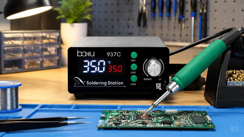
The BA-937C soldering station addresses this challenge with three preset buttons and a clear LED digital display showing the active temperature. Operators can switch between stored settings with a single button press instead of re-dialing a knob each time. This digital readout and preset arrangement is intended to reduce guesswork, helping protect printed circuit board copper layers during delicate component changes.
Uneven thermal expansion during hot air rework creates mechanical stress across logic boards. When top-side heat expands the board faster than the unheated bottom side, the substrate can bend. This board warpage risks lifting corner solder balls on fine-pitch BGA packages, creating hard-to-spot joint fractures.
| Engineering Specification | Fixture Detail |
|---|---|
| Board Clamping Range | 10 mm to 72 mm (Adjustable) |
| Platform Heat Resistance | Up to 500°C (Toughened Glass) |
| Rotational Freedom | 360° Rotation |
| Substrate Compatibility | Smartphones, Tablets, and Smartwatch Logic Boards |
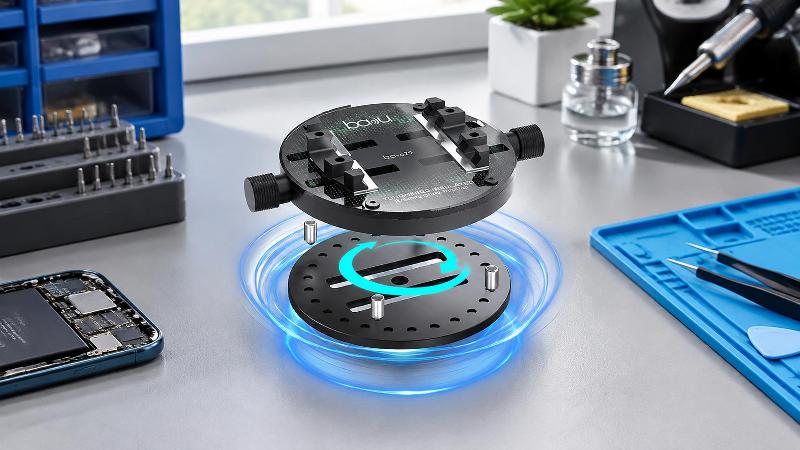
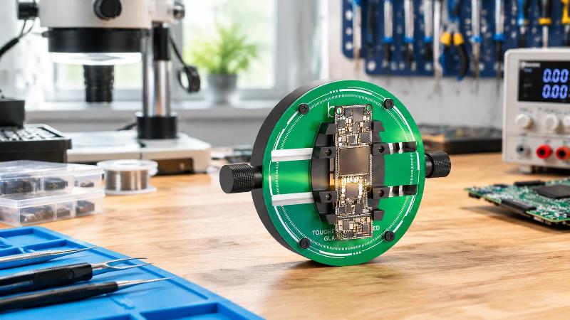
According to the supplied product specifications, the motherboard fixture in this collection offers a 10-72mm clamping range and a toughened glass panel rated to withstand temperatures up to 500°C, which is intended to help keep boards flat and support hot air rework safely. The fixture also rotates 360°, which can let operators view and access a clamped board from different angles under a microscope; the supplied specifications do not detail how clamp tension behaves during rotation, so that detail is left to the equipment’s own instructions.
Soldering microelectronics requires precision hand tools alongside heating equipment. Modern consumer devices use tight tolerances, internal seals, and hidden retention clips that can buckle under crude mechanical force. Technicians need non-marring pry tools and exact driver geometry before applying heat to board assemblies.
High-Precision Enclosure Disassembly: Using a pry set with blade profiles around 0.1 to 0.2mm, as specified in the supplied product data, allows technicians to work through adhesive gaskets with less risk of denting aluminum enclosures or puncturing internal batteries.
Controlled Fastener Removal: Working with a 41-in-1 electric screwdriver kit helps ensure drive bits match screw recesses precisely, reducing the chance of stripped heads on small internal fasteners.
Chemical Oxide Stripping: Applying active rosin or synthetic flux helps clear surface oxidation, supporting cleaner wetting of pad surfaces by molten solder.
Alloy Deposition for Rework: The supplied product information describes a solder paste and flux kit intended for board-level repair work. Using paste-form solder alongside flux can help technicians deposit alloy onto small pads during component rework, though the precision needed for BGA reballing specifically will depend on the operator’s technique and the process being followed.
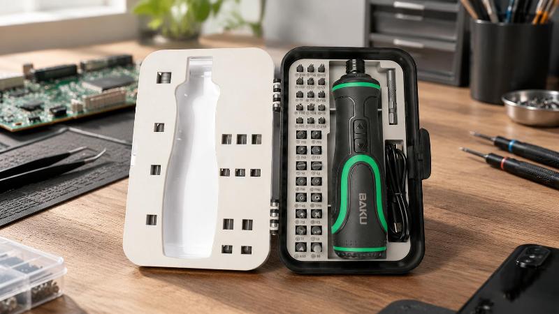
Compact mobile devices concentrate considerable computing power into tiny, multi-layer circuit boards. Technicians working on these boards face microscopic board traces, stacked circuit boards, and components packed tightly beneath metal electromagnetic shields. A slight hand slip or inaccurate thermal profile can easily damage neighboring components.
Baku has been active in the electronic repair industry for more than 20 years, and we offer professional soldering equipment and precision tools aimed at these delicate mobile and computer repair challenges. Pairing a fast-recovery soldering station with ultra-fine conical or micro-chisel tips can help technicians work near ground-plane pads with less risk of bridging nearby components. Repair kits that pair a stable soldering station with fine, sub-millimeter prying tools are built to help technicians tackle compact mobile logic boards with more confidence.
Integrated circuit packages with bottom-side pads, such as quad-flat no-leads and ball grid arrays, prevent direct contact with soldering iron tips. Removing and refitting these devices requires even convective heat and precise physical alignment to help ensure all joints reflow together.
Industrial assembly benches handle a wider range of thermal masses than dedicated micro-repair stations. Technicians working on these lines may solder multi-pin through-hole connectors, thick gauge wiring, and heavy power components alongside delicate surface-mount chips. These mixed assemblies demand versatile thermal performance from their soldering gear.
Soldering heavy terminals generally calls for heating cartridges with sufficient power reserve to avoid excessive temperature creep during idle periods. Using broad chisel, bevel, or knife-edge tips increases contact surface area, speeding up heat transfer into large copper planes. This approach helps operators solder thick power connections quickly, reducing the time nearby internal components spend absorbing heat.
Soldering tips feature a composite construction: a thermally conductive copper core covered by an electroplated iron shell, chrome plating, and a tinned working surface. Exposing this tinned surface to atmospheric oxygen at high temperatures forms tough iron oxides that repel liquid solder alloys.
Applying high heat locally to multi-layer printed circuit boards creates steep thermal gradients through the substrate thickness. The fiberglass substrate expands along its Z-axis at a different rate than vertical copper vias. Without proper heat control, this thermal stress can shear internal vias and cause permanent board failure.
The specific preheat, soak, and reflow temperatures that are safe for a given board depend on the board’s layer count, the components mounted on it, the solder alloy in use, and any process instructions supplied by the component or board manufacturer. Rather than applying a single fixed temperature sequence to every job, technicians should follow the heating profile recommended for the specific alloy and components involved, and consult the equipment manual for staged heating or preheating features.
A cautious, staged approach to heating, moving from a lower ambient-adjacent temperature toward the working reflow temperature rather than applying full heat immediately, is a widely used practice for reducing thermal shock. Letting the board cool gradually after rework, rather than moving or quenching it immediately, similarly helps limit stress on the substrate and nearby joints while the solder fully solidifies.
Lead-free solder alloys do not all share a single melting point; SAC305, for example, has a melting range of roughly 217°C to 220°C, and other common lead-free alloys melt at somewhat different ranges. Many technicians use an iron setpoint somewhere between 300°C and 370°C as a starting point, but this is not a universal setting. The right setpoint for a given job depends on the alloy, the tip in use, the thermal mass of the joint, and the component’s heat tolerance, so it is worth checking the solder manufacturer’s guidance and the equipment documentation rather than defaulting to one fixed number. Setting a station temperature too high for the task risks charring the flux before it can strip surface oxides, which can lead to dull, brittle solder joints.
Soldering stations with feedback-based temperature control use an internal sensor to track the tip temperature and adjust power output when that temperature drops. When an iron tip touches a cooler solder joint, a responsive station can increase power output quickly to limit how far the tip temperature falls. A cold solder joint typically results from insufficient heat reaching the joint, which leaves the solder poorly wetted to the base metal and often gives it a dull, grainy appearance rather than a smooth, bright fillet. Maintaining adequate, stable heat at the joint through responsive temperature control can help the solder wet properly and reduce the chance of this kind of defect.
Some semiconductor devices rely on extremely thin gate dielectrics that are sensitive to electrical overstress, and a static discharge or stray leakage current passing through a circuit board can damage these structures. An ungrounded soldering iron can accumulate static electrical charge or pass stray voltages into a board being worked on. The supplied product information describes relevant equipment in this collection as ESD-safe, though it does not detail the specific grounding construction or impedance values involved. Readers working in ESD-sensitive environments should check the individual model’s documentation and verify it against the applicable ESD standard and program requirements before relying on it to protect sensitive components.
Desoldering small surface-mount passives generally calls for lower airflow velocities paired with appropriately sized reducing nozzles. Excessive airflow can create lateral air currents that scatter nearby components across the board surface. The supplied specifications list an airflow capacity of up to 120L/min for some hot air systems in this soldering equipment collection; how much of that capacity to use depends on the specific model and the task, with lower settings generally suited to small passives and higher settings reserved for larger thermal loads such as ground shield cans or thick copper connectors.
Motherboard fixtures built with toughened glass panels, such as the one in this product lineup, are rated by the supplied specifications to withstand temperatures up to 500°C. Standard plastic fixtures can soften under hot air streams, shifting the board position mid-repair. A stable glass fixture is intended to hold a motherboard firmly between its clamping jaws, helping keep components steady under the microscope throughout reflow.
Maintaining a successful electronics assembly and rework operation requires precise thermal management at every step. Choosing capable soldering equipment turns microelectronic repair from an unpredictable gamble into a more controlled, repeatable process. From fast-recovery soldering stations and controlled hot air blowers to heat-resistant rotating fixtures, each tool serves a specific role in managing thermal energy. Equipping your workbench with dependable soldering equipment and quality auxiliary tools, and following the alloy and component manufacturer’s guidance rather than a single fixed temperature rule, helps protect sensitive components, reduce common soldering defects, and support better board yield across each assembly cycle.

Technical Guide to Electronic Soldering Equipment: Thermal Dynamics, Architecture, and Selection Fra
Choosing precision soldering equipment involves balancing heating methods, thermal control, ESD protection, and auxiliary tools for reliable board-level rework.

Digital Microscope Guide for Electronics Repair and Precision Soldering
Choosing a digital microscope for electronics repair means balancing optical zoom, working distance, latency, lighting, and bench stability for accurate rework.

The Engineering Guide to Soldering Equipment: Precision Bench Architecture and Microelectronics Rewo
Choosing soldering equipment with precise thermal control, ESD safety, and proper fixtures reduces board damage and improves rework reliability.

Choosing the Right Electronic Repair Equipment for Professional Service Centers
Professional electronic repair equipment including soldering stations, rework fixtures, and precision tools enables efficient, high-quality device repairs in service centers.
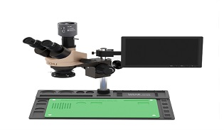
Stereo Microscope Price Guide: What Affects the Cost?
Discover what affects the price of a stereo microscope, including magnification, optical quality, digital features, lighting systems, and build materials. Learn how to choose the right model for electronics repair and precision inspection.
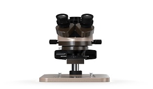
Stereo Microscope Uses: From Science Labs to Electronics Repair
Discover the key applications of stereo microscopes in biology labs, education, micro-soldering, and PCB repair. Learn how 3D magnification improves precision for scientific research and electronics technicians.

STAY CONNECTED